See our latest projects and be updated with recent news and features
happening in the world of pneumatic conveying, materials handling
and industrial vacuum systems.
See our latest projects and be updated with recent news and features
happening in the world of pneumatic conveying, materials handling
and industrial vacuum systems.

Tuesday, November 14, 2023
Before we get into how to handle rotary airlock valve leakage we need a solid understanding of what a rotary airlock valve is and how it works.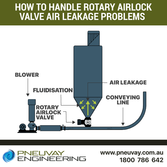
How to handle rotary airlock valve leakage with some effective solutions
Transferring powered material from a hopper in fixed and controlled amounts can be achieved by integrating a rotary airlock valve to a pneumatic conveying system. Rotary valves provide an airlock between a hopper or storage vessel connected above it, and the pressurised pipe used to pneumatic convey material connected beneath it.
An internal rotor within the valve rotates to discharge (metering) powdered material from the hopper or storage vessel into the conveying pipe. The rotor is to provide an air seal between the hopper or storage vessel and the conveying pipe. This air seal is needed to maintain the pressure of the conveying pipe used to transport the material.
The size and rotation speed of the rotor are the two factors governing the throughput of powdered material through the valve. For typical pneumatic conveying applications it is recommended that the volumetric filling capacity be made to, at most, 70% of rotary valve volume. Further, the maximum rotor speed should be around 35 rpm. These may, however, vary according to factors pertinent to the particular application.
Our rotary airlock valves are made in many sizes and speeds. Feel free to contact us if you need help selecting a rotary valve for your situation or read more on factors affecting the material feed rate of a rotary valve.
There are two main types of rotary valves supplied by Pneuvay.
The first type of rotary airlock valve has a configuration where the conveying pipes are connected to and from the end plate. This type of valve is used solely for pneumatic conveying and is ideal when conveying non-abrasive powders such as flour.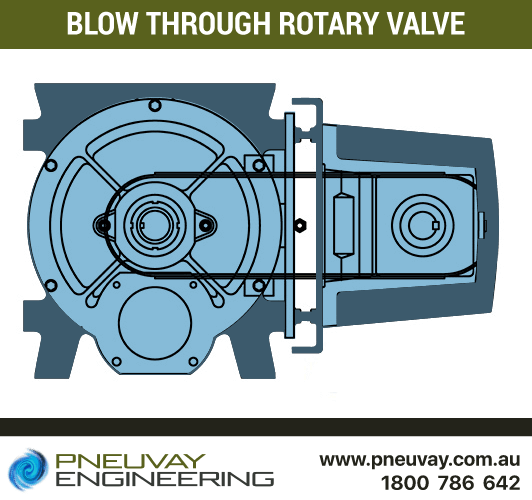
Design of blow through rotary valve diagram as supplied by Pneuvay
The second type of rotary valve is often used to dispense material from bins and hoppers. It is most often used in systems with dust collector hopper discharges that require a seal between atmosphere and vacuum system. This type of valve can be used in pneumatic conveying, however an ancillary pipe manifold to connect to the conveying pipe has to be added underneath the valve.
If you think you need one of these rotary valves, talk to us at 1800 786 642 or contact us online.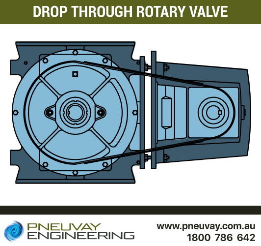
Design of drop through rotary valve diagram as supplied by Pneuvay
We are able to calculate, accurately and easily, the appropriate valve to provide the material feed rate required by your application. The factors we take into account when doing such calculations include:
The efficiency of feeder volume for materials less than 500kg/m3 is 60%. Over 500kg/m3 is 70% and over 1000kg/m3 is more than 70%. The rotor speed has a maximum of 35 rpm, however this can be increased in certain situations.
Contact us and we'll be glad to go over with this calculation with you.
There are other factors that must be considered to ensure efficient material feed rate. These factors are specific to the properties of the material and include:
The rotor airlock valve provides an air seal between the hopper or storage vessel and the conveying pipe. It is, however, not airtight. The blades of the rotor have a small gap between the blade tip and the internal casing of the rotor. This gap is called the 'rotor tip-to-housing clearance.'
This clearance is needed so the rotor can turn without rubbing against the casing. As the rotor turns, a small amount of air leaks through the small gap into the hopper or storage vessel above the rotary valve. The air leakage is driven upwards through the valve from the pressurised pipe connected underneath it.
Bulk materials handling experts have developed and designed several solutions to reduce the rotary airlock valve air leakage. These include the following:
This design shows the rotary airlock directly attached to a storage vessel. This allows the valve to act both as airlock and metering device. Further, this type of installation requires the least amount of equipment and headroom. A direction connection is the most common way to fit a rotary valve and must be used in situations in which a small amount of air leakage can be tolerated.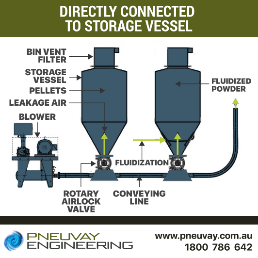
Model design of rotary valves directly connected to storage vessel
This design incorporates the use of a surge hopper and dedicated vent filter to the rotary airlock valve. It is one of the surest ways to direct leakage air to the atmosphere rather than into the storage vessel.
Although effective, there are some complications with this design. The use of static sock filters without including a cleaning facility may result in accumulated dirt. This will, in turn, increase the airflow resistance and decrease performance. Further, the use of a flood-fed option when handling the material can cause issues. Air leakage can fluidise the material and cause the pressure in the storage vessel from the static head of material to equalise with the level in the surge hopper. This can result in overfilling the surge hopper and block the filter for the vent.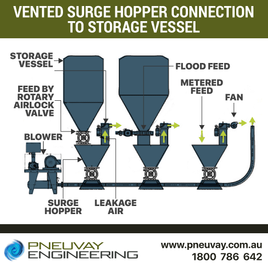
Model design of rotary valves with vented surge hopper
This system design uses a vented surge hopper without a dedicated vented filter. As a replacement to the filter, a vent pipe, hopper vent stub and fan are added to the system. It is notable that air is not allowed to pass together with the materials, rather it is directed to pass through the vent pipe. This prevents the formation of gas bubbles. However, this approach only works with specific types of materials.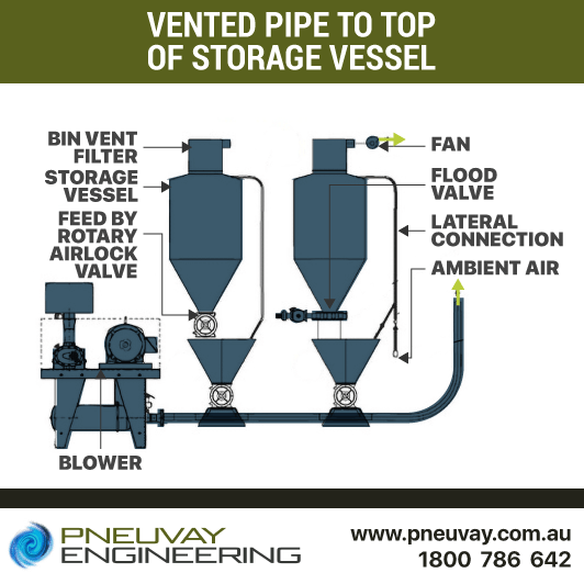
Model design of rotary valves with vented pipe to top of storage vessel
This system design requires the use of a vented hopper. It prevents venting leakage air by collecting the dust through the central dust collection system. Rather than relying on the leakage air volume, it relies on the air volume produced by the fans of the dust collection system. Although effective with low value materials, the amount of entrained particles, which are easily collected together with the dust particles and discarded as waste, doesn't make it ideal for conveying high value materials.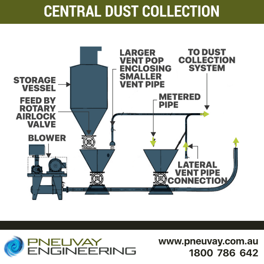
Model design of rotary valves in central dust collection system
This design makes use of an eductor to capture rather than vent air leakage. This approach provides the necessary air volume to handle heavier material.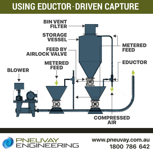
Model design of rotary valves using eductor driven capture system
This design requires the use of an airlock valve and body vent, which produces two airlocks. These airlocks are then used to pressurise the empty rotor pocket and air leaking through the rotor tip-to-housing clearance. As a result industries requiring a larger volume of pressurised air have a more efficient airlock system, which will increase fill efficiency.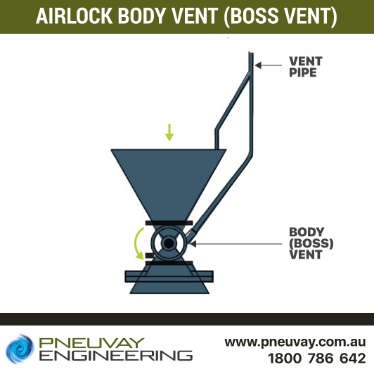
Model rotary valve airlock body vent design (boss vent)
Many years have passed since some initial solutions were published relative to how best to handle rotary airlock valve air leakage issues. Much has changed and improved in the pneumatic conveying industry; however, the airlock valve leakage remains a common problem for some. At Pneuvay we are able to study your industrial application needs and design the best solution to deliver the most efficient, reliable discharge of powdered materials into a pneumatic conveying system.
We understand that no two systems are ever the same. We take the time to understand your specific needs so we can design the most effective solution for your material conveying requirements and best address any performance issues from air leakage. Contact us online and schedule an appointment with us.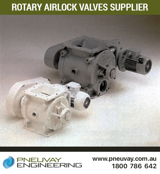
Rotary airlock valves supplied by Pneuvay
Get social with us and see the latest news items from:
Vortex Global is proud to appoint Pneuvay Engineering as its sole agent for New Zealand.
Read on to find out how this set a new standard for bulk material handling solution for Australia and New Zealand.
Pipe and Tube Compression Couplings
Industrial Dust Collectors Systems
Dust Collectors Filters, Cartridges and Bags
Pneuvay Engineering Pty Ltd - Copyright 2020
ABN 49 006 027 541
