See our latest projects and be updated with recent news and features
happening in the world of pneumatic conveying, materials handling
and industrial vacuum systems.
See our latest projects and be updated with recent news and features
happening in the world of pneumatic conveying, materials handling
and industrial vacuum systems.

Friday, August 27, 2021
We continue with our case study to examine the materials flow and operation of the chocolate milk powder handling and blending plant. We give an overview of how materials are transferred within and between these stages and a detailed description of the unloading stage of the plant.
The food processing plant receives and weighs minor ingredients (premix), along with several raw materials (processed sugar, creamer, cacao, whey and milk powder). It then blends these into a final product and continuously dispenses this for packing. The premix is colouring and flavouring is used to make a specific final product.
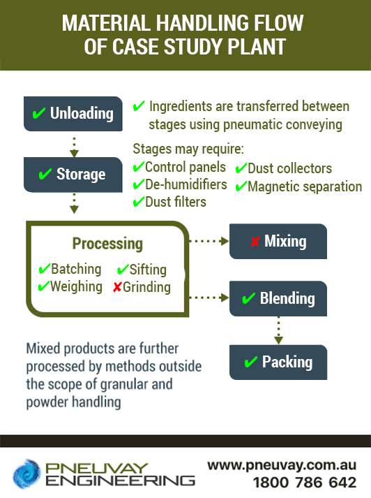
A modular structure is used to easily describe how materials flow through a given food processing plant. The flow is broken down into an ordered sequence of several connected and distinct production stages. The modular structure of material flow that applies to this particular processing plant are shown in the diagram below.

Material handling flow of chocolate milk powder food processing plant in the case study
The stages and their order for this particular plant are as follows:
This particular plant does not have a mixing stage, only a blending stage. It is typical for powdered food processing plants to have only one or the other. More on the differences between mixing and blending in powder food processing. Further, it does not use any grinding as part of its processing. The materials received by the plant need to be ready for blending as is and only require sifting.

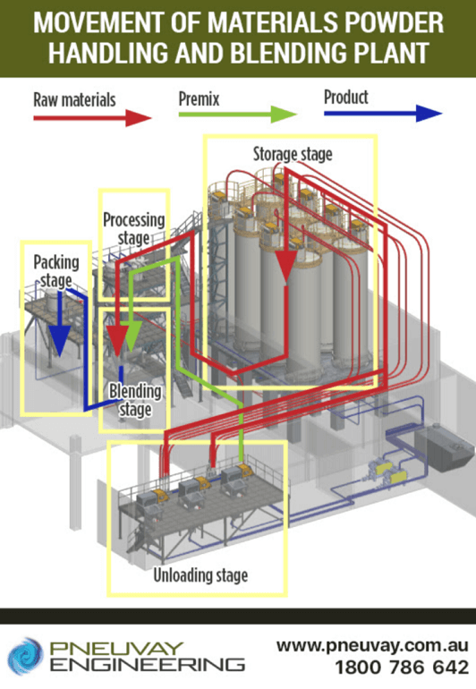
Material flow throughout the powder handling and blending plant
Small bags of material (powdered food ingredients) are brought into the plant and unloaded. Most of the materials (raw materials) are transferred to the storage stage. A small amount, however, of material (minor ingredient) is fed directly into the processing stage for weighing.
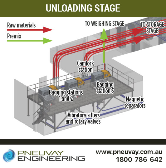
The raw materials and minor ingredients for the final product are mechanically conveyed into the bag tipping station area from the ground floor. The bags are manually dumped into each of the three tippers in 25kg or 50kg lots. They are then dropped into a corresponding vibratory sifter below. There is a chain hoist for each bag tipping station to handle one tonne large or bulk bags if needed. The bag station area has a packaging waste removal machine that efficiently takes away the emptied bags.
Each station has an aspiration unit for dust collection. This is important, as the bag tipping generates significant levels of dust. Emptying the small bags generates up to 100g of dust per bag. Similar dust concentrations are generated when big and bulk bags are emptied. The aspirators have a self-cleaning mode to keep maintenance to a minimum. The material flow and recipe settings are managed from the main panel (SCADA) in the control room.
Bag tipping stations 1 and 2 are multi-purpose and intake several types of raw materials. Station 1 feeds silos 1 to 4, while station 2 feeds silos 5 to 8. They each have a Human Machine Interface (HMI) that shows what raw material is coming next and the silo it is next to fill. The HMIs are used to notify the operators; they are not control panels. These two stations have the flexibility to transfer any of the raw materials to any of the eight silos at any time. The transfer uses lean phase pressure conveying with cool dry air from the nearby dehumidifying unit, booster fan and two pressure blowers. Bag station 3 intakes minor ingredients (premix) and transfers it to weighing hopper 1. It does this using lean phase vacuum conveying from vacuum pump 1.
Before conveying into the plant through the 316 stainless steel three-inch pipelines, the raw materials and minor ingredients are sieved by vibratory sifters to remove any oversized particles. The sifted powders are then meted out into the pipeline with rotary valves. The pipework taking air or vacuum to the rotary valves makes use of short radius pipe bends. When needed, these pipelines are purged, using Argon to remove moisture.
Raw materials from the rotary valves under bag tipping station 1 and 2 are transported to silos using boosted air processed by the dehumidifier from the pressure blowers. The minor ingredients from the rotary valve under bag tipping station 3 are transported to the weighing hopper 1 using vacuum from vacuum pump 1.
The vibratory sifters are connected to the rotary valves with BFM flexible connectors and spigots. The rotary valves are custom made by our engineering group (Pneu Powder Systems). They are used to dispense materials from the vibrating sifter to the attached pipework below for conveying into the plant. These 304 stainless steel rotary valves are drop-through sanitary models with heavy duty outboard bearings. They have ANSI flanges, use a chain drive with its gearbox, and are air purged shaft-sealed.
A large dehumidifier unit, booster fan and two powerful pressure blowers are used to generate cool dry air. This is used for pressure conveying throughout the powder-blending plant. Pressure blowers are also known as positive blowers.
The booster fan increases the pressure (output) of cool dry air for pneumatic conveying throughout the plant. This fan is in the same room as the blowers, but is connected to and fed air from the dehumidifier unit in the neighbouring room. The booster fan runs all the time and uses a custom-engineered intake manifold.
One pressure conveying section (lean phase pressure) powered by the dehumidifier and booster fan is between the unloading and storage stages where cool dry air:
The other pressure conveying section (dense phase vacuum) uses this cool dry air to help drive the process and prevent the condensation in the pipeline.
Magnetic separators are inline on the pipelines that pass under the vibratory sifters and rotary valves below bag tipping stations 1 and 2. They remove metal particles less than 30 micrometres in size that have somehow made their way into the raw materials. They use state-of-the-art technology to provide high separation yields and have a compact layout requiring only a minimal amount of space. These magnetic separators have high gauss values and are easy to clean and maintain.
There is no magnetic separator on the pipeline that passes under the vibratory sifter and rotary valve for bag tipping stations 3. The minor ingredient is a manufactured product previously screened by metal detectors when it was produced at another processing plant.
The camlock station is used to control flow of raw materials from bag tipping stations 1 and 2 to the eight silos and minor ingredients from bag station 3 to weighing hopper 1. The conveying rate through the cam station is five to seven tonnes per hour. There are two flexible hoses for the raw material lines and six flexible hoses supplying cool dry air to the top of storage silos. The ports for the cam station have a proximity sensor detecting which silo has been set to fill when product is flowing from bag tipping stations 1 and 2.
We have a set of pictures showing the equipment used in the unloading stage, a detailed description of what it does and how it integrates into the plant.
Check out the following in our photo gallery section:

Unloading stage of powder handling and blending plant
This example of this powder handling and blending plant project is detailed and broken into several major sections including:
We also has a list of other food processing plants case studies completed by the engineering group.
Pneuvay, with its connection to the Pneu Powders Systems group, is a market leader in material handling for powder handling and blending plants. We are able to provide engineering services locally in Australia and New Zealand. However, we do cover the Asia-Pacific and Middle East. Feel free to contact us if you need assistance with material handling for powder handling and blending plants. Call on 1300721458, contact us with our online form or message us on our Facebook page.
Get social with us and see the latest news items from:
Vortex Global is proud to appoint Pneuvay Engineering as its sole agent for New Zealand.
Read on to find out how this set a new standard for bulk material handling solution for Australia and New Zealand.
Pipe and Tube Compression Couplings
Industrial Dust Collectors Systems
Dust Collectors Filters, Cartridges and Bags
Pneuvay Engineering Pty Ltd - Copyright 2020
ABN 49 006 027 541
